마하젠다 간섭계 구축하기
마하젠다 간섭계란?
마하젠다 간섭계는 두 개의 시준된 광선 사이의 상대적 위상 변화를 측정하는 간단한 간섭 측정기입니다. 이 위상 변화는 작은 변위, 투과형 광학 부품의 투과 파면 오차, 투명 물질의 굴절률, 풍동에서의 공기 흐름 등을 확인하는 데 사용될 수 있습니다.
마하젠다 간섭계는 레이저와 같은 간섭 광원, 두 개의 빔스플리터 그리고 두 개의 미러로 구성되어 있습니다(그림 1 및 그림 2 ). 먼저, 첫 번째 빔스플리터를 사용하여 광원을 두 개의 경로로 나눕니다. 두 빔은 각각 동일한 광경로 길이를 가지며, 이는 이동한 거리에 통과한 매체의 굴절률을 곱한 값입니다. 각 빔은 미러에서 반사되고 두 번째 빔스플리터에 의해 재결합됩니다. 두 빔의 광경로 길이가 광원의 간섭 길이보다 짧은 경우 간섭 무늬가 생성됩니다. 광원의 간섭 길이는 매우 짧을 수 있기 때문에 정밀 부품과 정렬이 중요합니다. 빔 경로 중 하나에 샘플을 배치하여 이를 측정할 수 있습니다. 최종적인 광경로 길이 차이는 간섭 무늬의 변화를 관찰하여 측정할 수 있습니다.
그림 1: 마하젠다 간섭계의 일반적인 광학 구조그림 2: 에드몬드옵틱스의 표준 부품으로 제작된 조립식 테이블탑 마하젠다 간섭계 시스템에드몬드옵틱스의 표준 부품을 사용하여 시스템 조립
아래 가이드를 따라 그림 2 에 표시된 것과 같은 시스템을 조립할 수 있습니다.
하위 어셈블리
각 광학 하위 어셈블리를 테이블탑 브레드보드에 추가할 수 있으며, 광학 레일을 통해 광축을 따라 쉽게 밀어 넣을 수 있습니다. 광학 레일의 캐리어에 배치된 작은 리니어 모션 스테이지 덕분에 광축 방향이나 직교 방향으로 쉽게 미세 조정할 수 있습니다.
옵티컬 베이스
재고 번호 제품명 수량
#54641 600mm x 300mm, Breadboard
1
#54929 500mm Length, Compact Optical Rail
2
광원
재고 번호 제품명 수량
#86848 Coherent® StingRay™ Laser Diode Module 1231490 | 520nm, 5mW
1
#86878 Coherent® 1263030 | Laser Controller with CDRH Key Lock + Power Supply
1
#18291 E-Series 19.1mm ID Adapter
1
#15866 25.0/25.4mm Optic Dia., E-Series Kinematic Mount
1
#72774 63.5mm Length, M6 and M6, Steel Post
1
#58973 76.2mm Length, M6 Thread, Post Holder
1
#58992 Post Collar
1
#16714 Dovetail Stage, 30mm SQ, Metric
1
#11164 30mm Length x 35mm Width, Compact Carrier
1
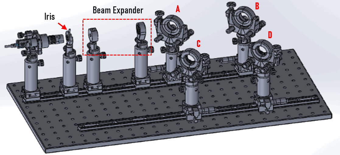
그림 3: 광원 하위 어셈블리아이리스 다이어프램
재고 번호 제품명 수량
#53914 30.8mm Outer Diameter, Mounted Iris Diaphragm
2
#58963 2.5" Length, 8-32 Stud, Steel Post
2
#58973 76.2mm Length, M6 Thread, Post Holder
2
#58992 Post Collar
2
#16714 Dovetail Stage, 30mm SQ, Metric
2
#11164 30mm Length x 35mm Width, Compact Carrier
2
그림 4: 아이리스 다이어프램 하위 어셈블리평면-오목(PCV) 렌즈 마운트
재고 번호 제품명 수량
#64552 6.0mm Optic Dia., Optic Mount
1
#48690 6mm Diameter x -15 FL, VIS 0° Coated, Plano-Concave Lens
1
#72774 63.5mm Length, M6 and M6, Steel Post
1
#58973 76.2mm Length, M6 Thread, Post Holder
1
#58992 Post Collar
1
#16714 Dovetail Stage, 30mm SQ, Metric
1
#11164 30mm Length x 35mm Width, Compact Carrier
1
그림 5: 평면-오목(PCV) 렌즈 마운트 하위 어셈블리평면-볼록(PCX) 렌즈 마운트
재고 번호 제품명 수량
#13787 25.0/25.4mm Optic Dia., SM1 Thin Mount, M4
1
#62573 25.4mm Dia. x 76.2mm FL, VIS 0° Coated, Plano-Convex Lens
1
#72764 63.5mm Length, M4 and M6, Steel Post
1
#58973 76.2mm Length, M6 Thread, Post Holder
1
#58992 Post Collar
1
#16714 Dovetail Stage, 30mm SQ, Metric
1
#11164 30mm Length x 35mm Width, Compact Carrier
1
그림 6: 평면-볼록(PCX) 렌즈 마운트 하위 어셈블리프로젝션 렌즈 마운트
재고 번호 제품명 수량
#13787 25.0/25.4mm Optic Dia., SM1 Thin Mount, M4
1
#47917 25mm Dia. x -25mm FL, VIS 0° Coated, Double-Concave Lens
1
#72764 63.5mm Length, M4 and M6, Steel Post
1
#58973 76.2mm Length, M6 Thread, Post Holder
1
#58992 Post Collar
1
#16714 Dovetail Stage, 30mm SQ, Metric
1
#11164 30mm Length x 35mm Width, Compact Carrier
1
그림 7: 프로젝션 렌즈 마운트 하위 어셈블리미러 포함 짐벌 마운트(2세트)
재고 번호 제품명 수량
#54999 25.0/25.4mm Optic Dia., Precision Gimbal Mount
2
#64015 25mm Diameter Enhanced Aluminum Coated, λ/10 Mirror
2
#72773 50.8mm Length, M6 and M6, Steel Post
2
#58972 50.8mm Length, M6 Thread, Post Holder
2
#58992 Post Collar
2
#66393 30mm, Side Drive, Standard Top, 0.5" Travel, Metric Micrometer
2
#11164 30mm Length x 35mm Width, Compact Carrier
2
그림 8: 미러 포함 짐벌 마운트 하위 어셈블리빔스플리터 포함 짐벌 마운트(2세트)
재고 번호 제품명 수량
#54999 25.0/25.4mm Optic Dia., Precision Gimbal Mount
2
#34413 25mm Diameter 50R/50T, VIS Wedged Plate Beamsplitter
2
#59759 50.8mm Length, M6 Stud, Steel Post
2
#58972 50.8mm Length, M6 Thread, Post Holder
2
#58992 Post Collar
2
#66393 30mm, Side Drive, Standard Top, 0.5" Travel, Metric Micrometer
2
#11164 30mm Length x 35mm Width, Compact Carrier
2
그림 9: 빔스플리터 포함 짐벌 마운트 하위 어셈블리전체 부품 목록
재고 번호 제품명 수량
#54641 600mm x 300mm, Breadboard
1
#54929 500mm Length, Compact Optical Rail
2
#11164 30mm Length x 35mm Width, Compact Carrier
10
#16714 Dovetail Stage, 30mm SQ, Metric
6
#66393 30mm, Side Drive, Standard Top, 0.5" Travel, Metric Micrometer
4
#58972 50.8mm Length, M6 Thread, Post Holder
4
#58973 76.2mm Length, M6 Thread, Post Holder
6
#58992 Post Collar
10
#59760 63.5mm Length, M6 Stud, Steel Post
2
#72764 63.5mm Length, M4 and M6, Steel Post
1
#72773 50.8mm Length, M6 and M6, Steel Post
2
#58963 2.5" Length, 8-32 Stud, Steel Post
2
#86848 Coherent® StingRay™ Laser Diode Module 1231490 | 520nm, 5mW
1
#86878 Coherent® 1263030 | Laser Controller with CDRH Key Lock + Power Supply
1
#15866 25.0/25.4mm Optic Dia., E-Series Kinematic Mount
1
#18291 E-Series 19.1mm ID Adapter
1
#53914 30.8mm Outer Diameter, Mounted Iris Diaphragm
2
#64552 6.0mm Optic Dia., Optic Mount
1
#48690 6mm Diameter x -15 FL, VIS 0° Coated, Plano-Concave Lens
1
#13787 25.0/25.4mm Optic Dia., SM1 Thin Mount, M4
2
#62573 25.4mm Dia. x 76.2mm FL, VIS 0° Coated, Plano-Convex Lens
1
#47917 25mm Dia. x -25mm FL, VIS 0° Coated, Double-Concave Lens
1
#54999 25.0/25.4mm Optic Dia., Precision Gimbal Mount
4
#64015 25mm Diameter Enhanced Aluminum Coated, λ/10 Mirror
2
#34413 25mm Diameter 50R/50T, VIS Wedged Plate Beamsplitter
2
마하젠다 간섭계 정렬하기
레이저, 조리개, 렌즈는 동일한 광축에 정렬되어야 합니다. 가장 좋은 상태는 이러한 부품이 광학 레일 위에서 이동하더라도 광축은 바뀌지 않아야 합니다. 광학 레일 캐리어에 설치된 스테이지는 레일 방향에 직각으로 수평 이동을 가능하게 합니다.
레이저 모듈 설치하기
어댑터(#18291 )를 사용하여 레이저 모듈(직경 Φ19.1mm)을 #15866 에 고정합니다.
그러면 레이저 각도를 쉽게 조정할 수 있습니다.
레이저 빔이 광학 레일과 평행하도록 마운트 각도를 조정합니다.
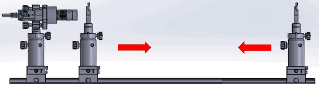
레이저 광축 정렬하기
조리개 하위 어셈블리를 사용하여 모든 시스템 부품의 광축 중심을 일정하게 유지합니다.
레이저가 조리개 중심을 향하게 합니다.
전체 범위에 걸쳐 레이저가 조리개 중심을 향하도록 키네마틱 마운트를 조정하면서 광학 레일을 따라 조리개를 밉니다.
그림 11: 레이저 광축 정렬하기
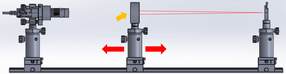
평면-볼록(PCX) 렌즈 광축 정렬하기
렌즈 유닛을 좌우로 밀면서 평면-볼록(PCX) 렌즈 광축을 긴 초점 거리에 맞춰 조정합니다.
포스트를 사용하여 렌즈의 높이를 조정하고 도브테일 스테이지를 사용하여 광축을 수직 방향으로 조정합니다.
그림 12: 평면-볼록(PCX) 렌즈 광축을 긴 초점 거리에 맞추기
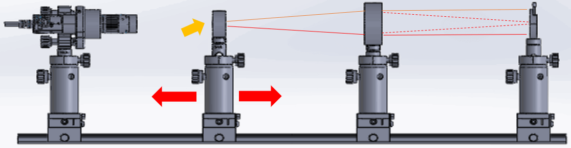
평면-오목(PCV) 렌즈 광축 정렬하기
초점 거리가 짧은 평면-오목(PCV) 렌즈를 광경로에 놓습니다.
렌즈 유닛을 좌우로 밀면서 광축을 조정합니다.
포스트를 사용하여 렌즈의 높이를 조정하고 도브테일 스테이지를 사용하여 광축을 수직 방향으로 조정합니다.
그림 13: 평면-오목(PCV) 렌즈 광축을 짧은 초점 거리에 맞추기
빔 익스팬더를 형성하도록 렌즈 배치하기
두 렌즈는 초점 거리의 합만큼 분리되어야 합니다. 이 경우, 간격은 76.2mm – 25mm = 51.2mm여야 합니다.
렌즈를 결합하여 빔의 직경을 원하는 크기로 확장하는 방법에 대한 자세한 내용은 표준 광학 부품을 활용한 빔 익스팬더 제작 방법 편을 확인하세요.
미광을 피하기 위해서는 반사율이 낮은 코팅 렌즈를 선택하는 것이 중요합니다.
그림 14: 두 개의 렌즈 하위 어셈블리를 조리개 앞에 배치하여 빔 익스팬더 형성하기
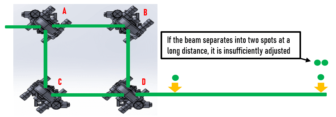
미러 및 빔스플리터 정렬하기
두 개의 광경로 길이는 동일해야 하며(또는 거의 동일해야 함), 무늬를 얻기 위해서는 최종 빔이 중첩되어야 합니다.
레이저를 두 개의 경로로 나누기 위해 빔스플리터를 A 위치에 배치하고, 빔을 재결합하기 위해 또 다른 빔스플리터를 D 위치에 배치합니다.
A-B-D와 A-C-D의 광경로 길이가 동일하도록 거리를 조정합니다.
미러/빔스플리터 마운트의 엣지가 빔을 차단하지 않도록 주의해야 합니다.
D를 투과한 빔이 D에서 반사된 빔과 중첩되어야 합니다.
두 빔이 D 바로 뒤에 그리고 D를 지나 레일 뒤쪽에서 중첩되도록 미러 위치와 각도를 조정합니다(그림 15 ).
그림 15: 미러 및 빔스플리터 정렬하기
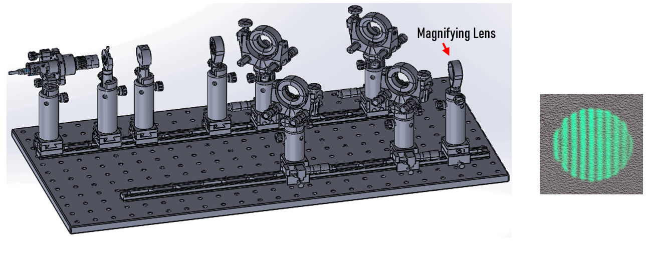
간섭 무늬 확인하기
D 뒤에 확대 렌즈를 추가하면 무늬를 더 쉽게 식별할 수 있습니다.
무늬를 얻기 위해 광학 레일의 스테이지 위치와 다른 부품의 정렬을 미세 조정해야 할 수 있습니다.
그림 16: 표준 부품으로 제작된 최종 마하젠다 간섭계 설정
기타 참고 문헌


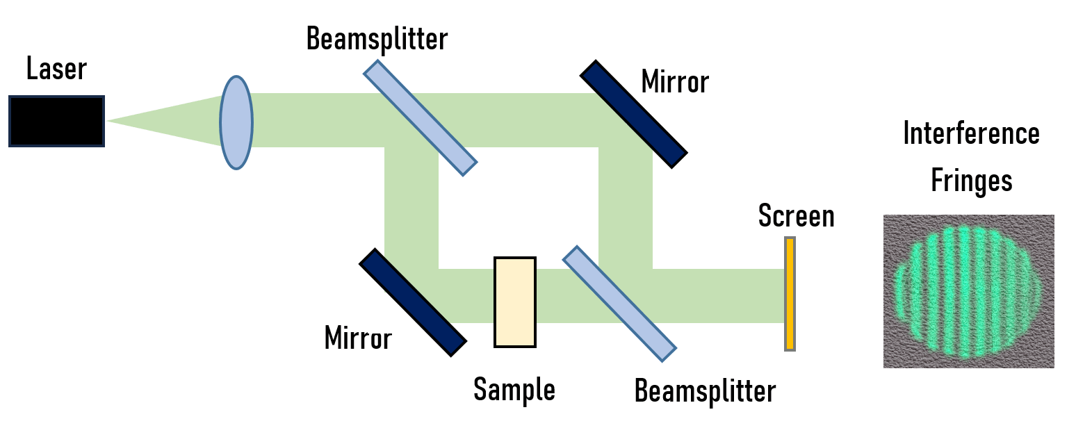

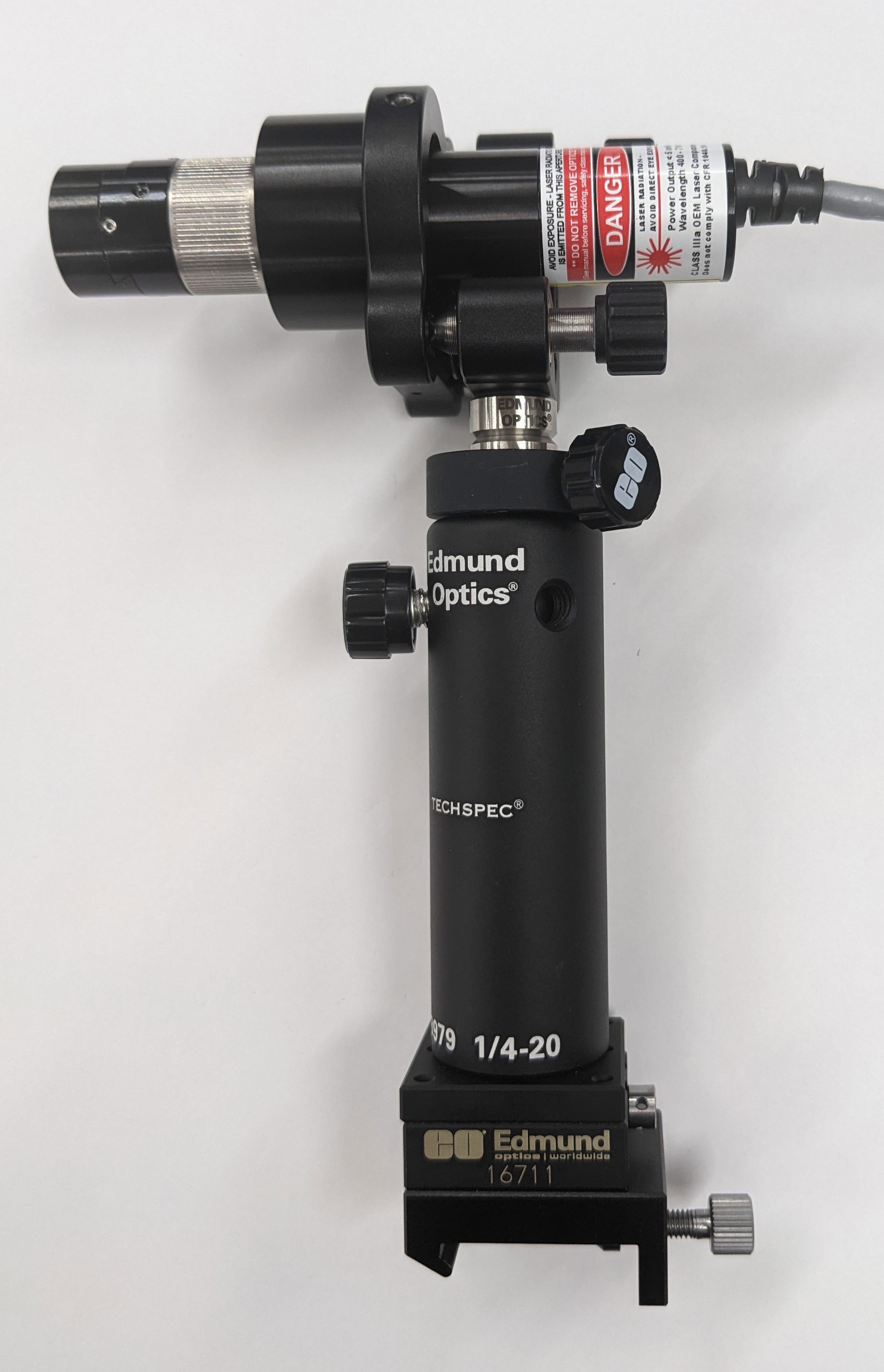
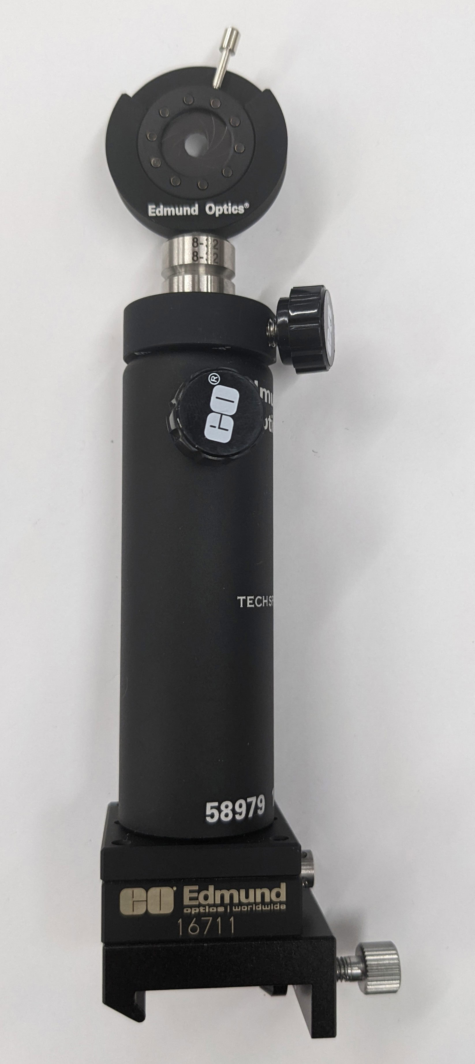

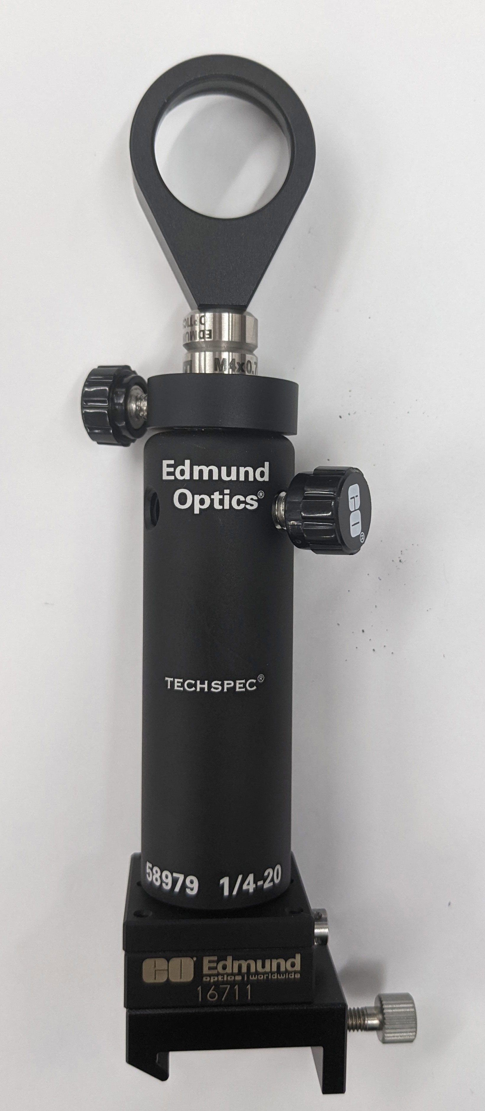
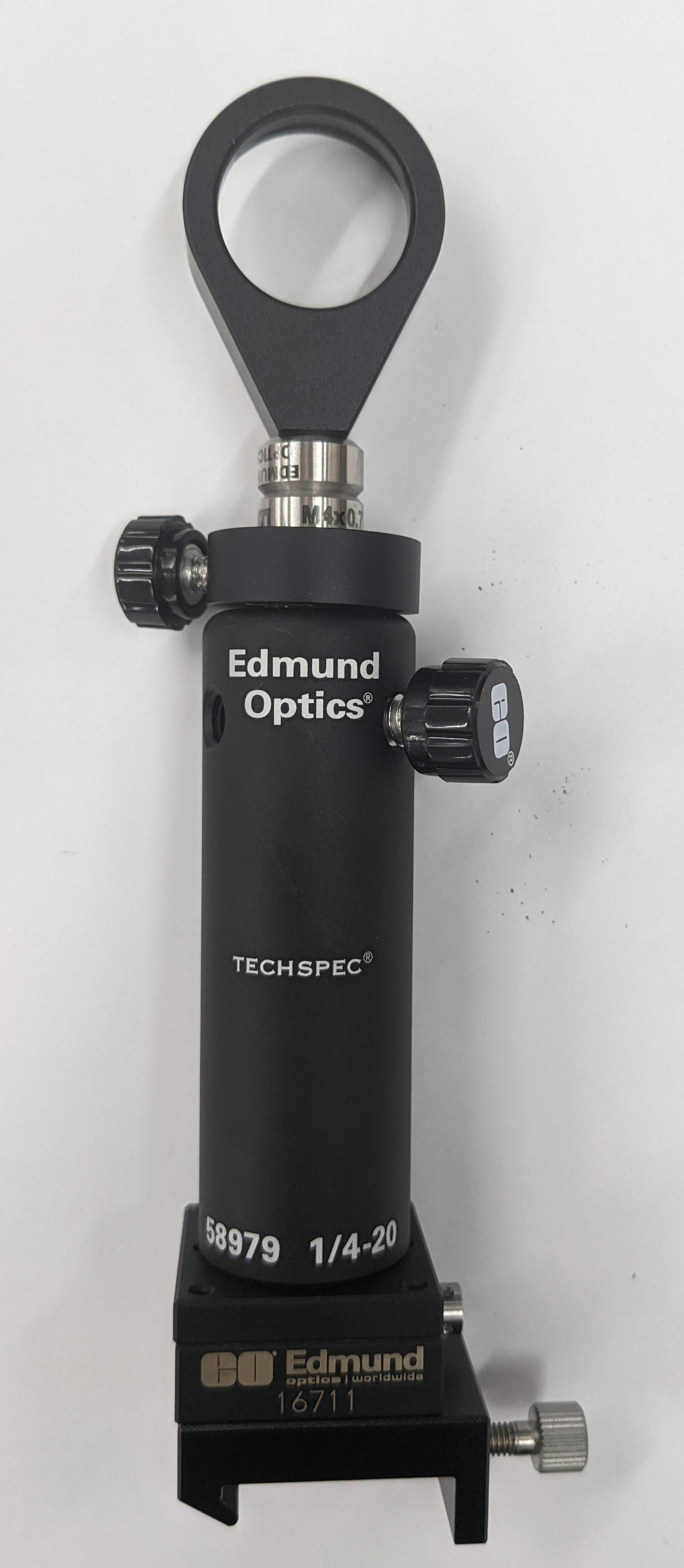
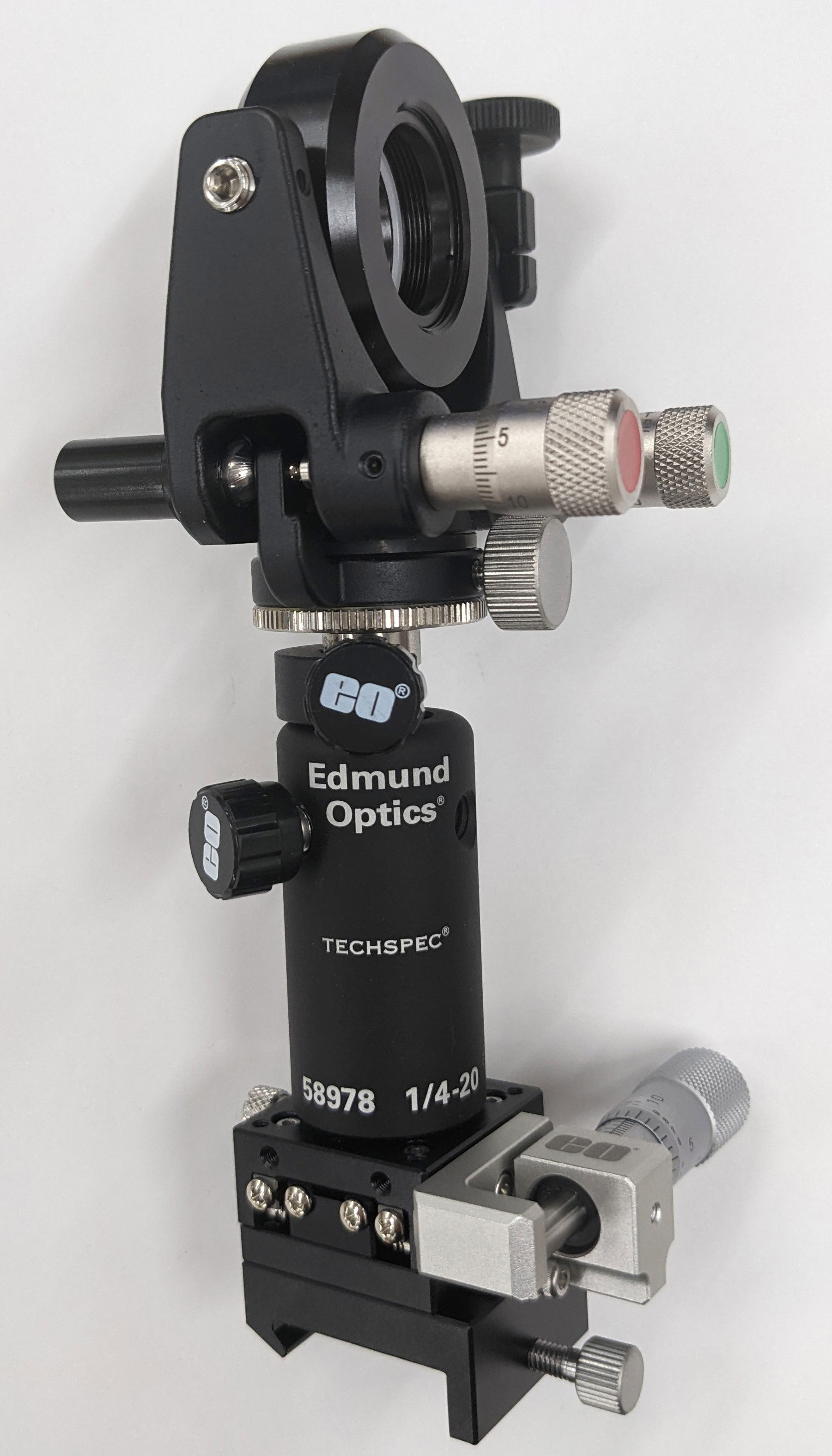
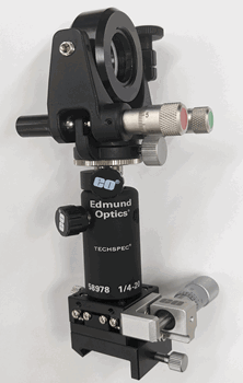
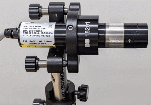 그림 10: 레이저 모듈 설치하기
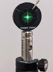


본사 및 지사별 연락처 확인하기
견적 요청 도구
재고 번호 입력 필요
Copyright 2023, 에드몬드옵틱스코리아 사업자 등록번호: 110-81-74657 | 대표이사: 이준호 | 통신판매업 신고번호: 제 2022-서울마포-0965호, 서울특별시 마포구 월드컵북로 21, 7층 (서교동, 풍성빌딩)
The FUTURE Depends On Optics®