


Gauging Depth of Field in Your Imaging System
Over the years, we have answered countless questions regarding lens performance. Of those questions, none have been more difficult to define than requests for depth of field. The reason for this difficulty has more to do with the vagueness of the question than with the inability to provide a measured or calculated value. Consider for a moment what depth of field tells us. It is the distance by which an object may be shifted before an unacceptable blur is produced. For depth of field to be properly stated, it should contain not only the displacement of an image, but also a specific resolution. The depth of field specification is further complicated by a type of keystoning aberration that often occurs. This result can dramatically affect linear measurements and therefore render depth of field unusable. In this article we will take a closer look at depth of field calculations and compare them to physical measurements using the DOF 1-40 depth of field gauge. The gauge, as we will see later, offers a unique look at what depth of field really means and how we as system designers may wish to quantify this parameter. A simple geometric approximation for depth of field is shown in Figure 1.0. The linear blur (required resolution) Bp, Bm and Bf can be expressed in terms of angular blur by the following equation.
Figure 1
Using similar triangles, a relationship can now be made between angular blur and the focus point,
where λ is the aperture of the lens. Solving for δ+ and δ—,
The derivation above is very specific to the intended resolution. However, many theoretical derivations of depth of field often assume the lens resolution to be nearly diffraction limited. The most popular of these derivations are based on microscope applications. A typical example for the total depth of field (δ+ + δ—) is shown below.
Where λ is the wavelength and NA equals the numerical aperture of the lens.
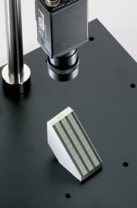
In order to study depth of field we have put together a simple macro system consisting of a 25mm fixed focal length lens, 8mm spacer and Sony XC-75 monochrome CCD video camera. The system was chosen not for its performance but rather for its common real world implementation. Measurements were performed using the DOF 1-40 target. The target allows us to measure depth of field at either 1, 10, 20 or 40 lp/mm over a maximum depth of 50mm. The flat field resolution of this system is approximately 15 lp/mm at 0.3X primary magnification. For purposes of our experiment, a blur spot resolution of 0.1 mm or 10 lp/mm was chosen. Depth of field measurements were taken at three aperture settings corresponding to f/2, f/4, and f/8. An important point should be noted about aperture settings. The f-number shown on most fixed focal length lenses is calculated with the object at infinity. As a result, we have adjusted our NA and therefore our aperture values for a 95mm working distance.
The values below highlight a number of points to consider. In general our calculated and measured delta d are fairly close. However, the displacement of the image due to defocus aberrations was not predicted by our calculations. This type of displacement error could certainly be problematic if the system contained an auto iris. If we compare our measured results to the delta-theory, we notice a significant variation. As we mentioned earlier, this variation is due to a false assumption concerning system resolution.
Another property that should be noted in our DOF 1-40 observations is the non-uniform magnification seen through the depth of field range. This is a very common problem in most lenses and, as we stated earlier, can yield significant errors if measurements are made throughout the full depth of field range. Edmund Optics provides several telecentric options to correct for this type of error.
In the end, it is the total performance of an optical system that counts. As a full service supplier and manufacturer of optics, illumination, CCD cameras, monitors, mounting, and electronic imaging related products, Edmund Optics has the knowledge and resources to look at your application as a total system. In fact, innovative tools such as the DOF 1-40 have come about from our own in-house need to quantify system performance. So if you are looking for individual components that can be integrated into your system or starting from scratch, our engineers are ready to help.
References
- Smith, Warren J. Modern Optical Engineering. 2nd ed. New York, NY: McGraw-Hill Education, 1990.

본사 및 지사별 연락처 확인하기
견적 요청 도구
재고 번호 입력 필요
Copyright 2023, 에드몬드옵틱스코리아 사업자 등록번호: 110-81-74657 | 대표이사: 이준호 | 통신판매업 신고번호: 제 2022-서울마포-0965호, 서울특별시 마포구 월드컵북로 21, 7층 (서교동, 풍성빌딩)
The FUTURE Depends On Optics®